Product Matrix
Barix Audio Product Matrix
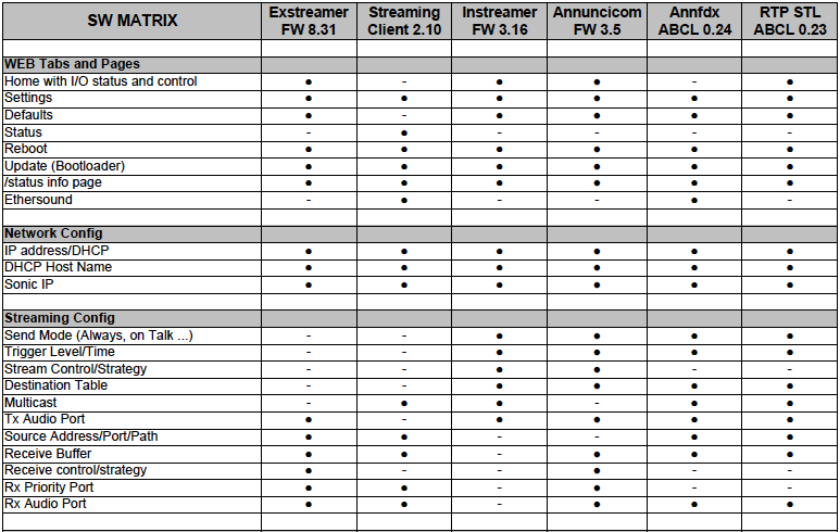
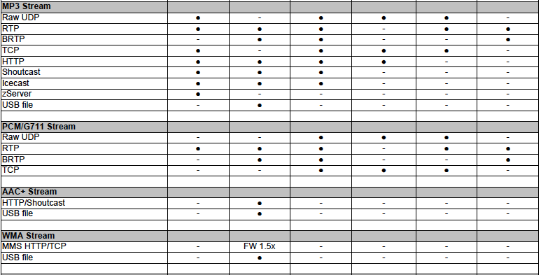
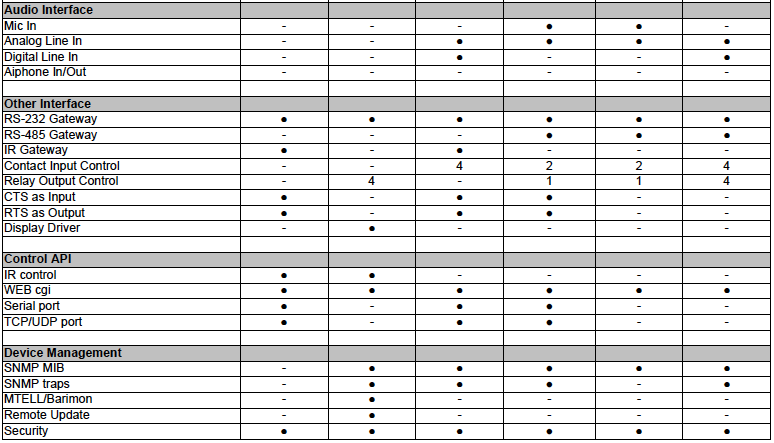
Barix audio products are a combination of HW capabilities versus SW functionalities. Almost any SW version can be loaded on any HW device. The attached tables help you to find out which combination best fits your requirements. First look at what HW device provides the right capabilities and then look at what SW version enables the required features.
Hardware Features
| Audio Codec | Ex 100 | Ex 110 | Ex 120 | Ex 200 | Ex P5 | Ex 500 | Ex 1000 | In 100 | Ann 100 | Ann 155 | Ann 200 | Ann 1000 |
|---|---|---|---|---|---|---|---|---|---|---|---|---|
| Audio module | IPAM 300 | IPAM 300 | IPAM 300 | IPAM 300 | IPAM 300 | IPAM 100 | IPAM 100 | IPAM 100 | IPAM 100 | IPAM 100 | IPAM 100 | IPAM 100 |
| PCM/G711 | dec | dec | dec | dec | dec | dec & enc | dec & enc | dec & enc | dec & enc | dec & enc | dec & enc | dec & enc |
| MPEG | dec | dec | dec | dec | dec | dec & enc | dec & enc | dec & enc | dec & enc | dec & enc | dec & enc | dec & enc |
| AAC | dec | dec | dec | dec | dec | |||||||
| WMA | dec | dec | dec | dec | dec | |||||||
| "dec" stands for decoding, "enc" for encoding | ||||||||||||
| Audio Interfaces | Ex 100 | Ex 110 | Ex 120 | Ex 200 | Ex P5 | Ex 500 | Ex 1000 | In 100 | Ann 100 | Ann 155 | Ann 200 | Ann 1000 |
| Microphone In (& Bias) | unbalanced | balanced | unbalanced | balanced | ||||||||
| Microphone Type | electret, coil | electret | electret, coil | electret, coil | ||||||||
| Mic Bias DC | 2.7 V | 3.4 V | 2.7 | 12 V sel | ||||||||
| Analog Input | stereo bal. | stereo bal. | stereo unb. | mono unb. | mono unb. | mono unb. | stereo bal. | |||||
| Analog Output | stereo unb. | stereo unb. | stereo unb. | stereo bal. | stereo bal. | mono unb. | mono bal. | mono unb. | stereo bal. | |||
| Headphone Output | ✔ | ✔ | ✔ | ✔ | ✔ | |||||||
| Speaker Output | 2 x 25W | 1 x 5W | 1 x 2W | 1 x 5W sup | 1 x 8W | |||||||
| S/P DIF Input | opt. & coax | |||||||||||
| S/P DIF Output | optical | |||||||||||
| AES/EBU Interface | in & out | |||||||||||
| Aiphone SUB I/F | ✔ | |||||||||||
| "unb." stands for unbalanced, "bal." for balanced,"sel" for selectable: either electret bias with current supervision or coil (no bias) with impedance test, "sup" for speaker supervision, | ||||||||||||
| Other Interfaces | Ex 100 | Ex 110 | Ex 120 | Ex 200 | Ex P5 | Ex 500 | Ex 1000 | In 100 | Ann 100 | Ann 155 | Ann 200 | Ann 1000 |
| Ethernet | 1 x RJ45 | 1 x RJ45 | 1 x RJ45 | 1 x RJ45 | 1 x RJ45 | 1 x RJ45 | 1 x RJ45 | 1 x RJ45 | 1 x RJ45 | 2 x RJ45 | 1 x RJ45 | 2 x RJ45 |
| RS-232 | ✔ | ✔ | ✔ | ✔ | ✔ | ✔ | ✔ | ✔ | ✔ | ✔ | ||
| RS-485 | ✔ | ✔ | ✔ | ✔ | ✔ | ✔ | ||||||
| Infared receiver | ext | ✔ | ✔ | ✔ | ext | ext | ext | ext | ext | ext | ext | ext |
| Infared output | ✔ | |||||||||||
| Dry Contact Input | 4 | 4 | 2 | 2 sup | 2 | 8 sup | ||||||
| Relay Output | 1 NO | 1 NO | 4 NO | 4 NO | 1 NO | 1 LED | 1 NO | 8 NO, 1 NC | ||||
| Flash Memory Interface | USB | USB | microSD | USB | USB | USB | USB | USB | ||||
| LCD Display | ✔ | ✔ | ||||||||||
| Status LEDs | ✔ | ✔ | ✔ | ✔ | ✔ | ✔ | ✔ | ✔ | ✔ | ✔ | ||
| I/O LEDs | 4 | 4 | 8 | |||||||||
| "ext" stands for external accessory IR Kit or VSC (Volume Source Control), "sup" for input supervision, "NO" for Normally Open contacts, "NC" for Normally Closed contacts, "LED" for LED driver instead of relay, | ||||||||||||
| Power Supply | Ex 100 | Ex 110 | Ex 120 | Ex 200 | Ex P5 | Ex 500 | Ex 1000 | In 100 | Ann 100 | Ann 155 | Ann 200 | Ann 1000 |
| DC Voltage range | 9..30 V | 9..30 V | 9..30 V | 24 V | 48 V | 24..48 V | 24..48 V | 9..30 V | 9..30 V | 24..48 V | 16..30 V, 48V | 2 x sup 24..48 V |
| AC Voltage range | 12..24 V | 12..24 V | 12..24 V | 12..24 V | 12..24 V | 16..24 V | ||||||
| PoE 802.3af | ✔ | ✔ | ||||||||||
| "sup" stands for voltage supervision | ||||||||||||
Device's Software Support Overview
| Ex 100 | Ex 110 | Ex 120 | Ex 200 | Ex P5 | Ex 500 | Ex 1000 | In 100 | Ann 100 | Ann 155 | Ann 200 | Ann 1000 | |
|---|---|---|---|---|---|---|---|---|---|---|---|---|
| Audio module | IPAM 300 | IPAM 300 | IPAM 300 | IPAM 300 | IPAM 300 | IPAM 100 | IPAM 100 | IPAM 100 | IPAM 100 | IPAM 100 | IPAM 100 | IPAM 100 |
| Exstreamer FW | ✔ | ✔ | ✔ | ✔ | ✔ | ✔ | - | - | ✔ | ✔ | ✔ | ✔ |
| Streaming Client | ✔ | ✔ | ✔ | ✔ | ✔ | ✔ | - | - | ✔ | ✔ | ✔ | ✔ |
| Instreamer FW | - | - | - | - | - | ✔ | ✔ | ✔ | ✔ | ✔ | ✔ | ✔ |
| Annuncicom FW | ✔ | ✔ | ✔ | ✔ | ✔ | ✔ | ✔ | ✔ | ✔ | ✔ | ✔ | ✔ |
| ABCL annunfdx | ✔ | ✔ | ✔ | ✔ | ✔ | ✔ | ✔ | ✔ | ✔ | ✔ | ✔ | ✔ |
| ABCL rtp stl | ✔ | ✔ | ✔ | ✔ | ✔ | ✔ | ✔ | ✔ | ✔ | ✔ | ✔ | ✔ |
Software Features Overview
| SW Package | Exstreamer FW | Streaming Client FW | Instreamer FW | Annuncicom FW | Annfdx ABCL | RTP STL ABCL |
|---|---|---|---|---|---|---|
| Version | 8.31 | 2.10 | 3.16 | 3.5 | 0.24 | 0.23 |
| WEB Tabs & Pages | Exstreamer FW | Streaming Client FW | Instreamer FW | Annuncicom FW | Annfdx ABCL | RTP STL ABCL |
| Home with I/O status/control | ✔ | ✔ | ✔ | ✔ | ✔ | ✔ |
| Settings | ✔ | ✔ | ✔ | ✔ | ✔ | ✔ |


